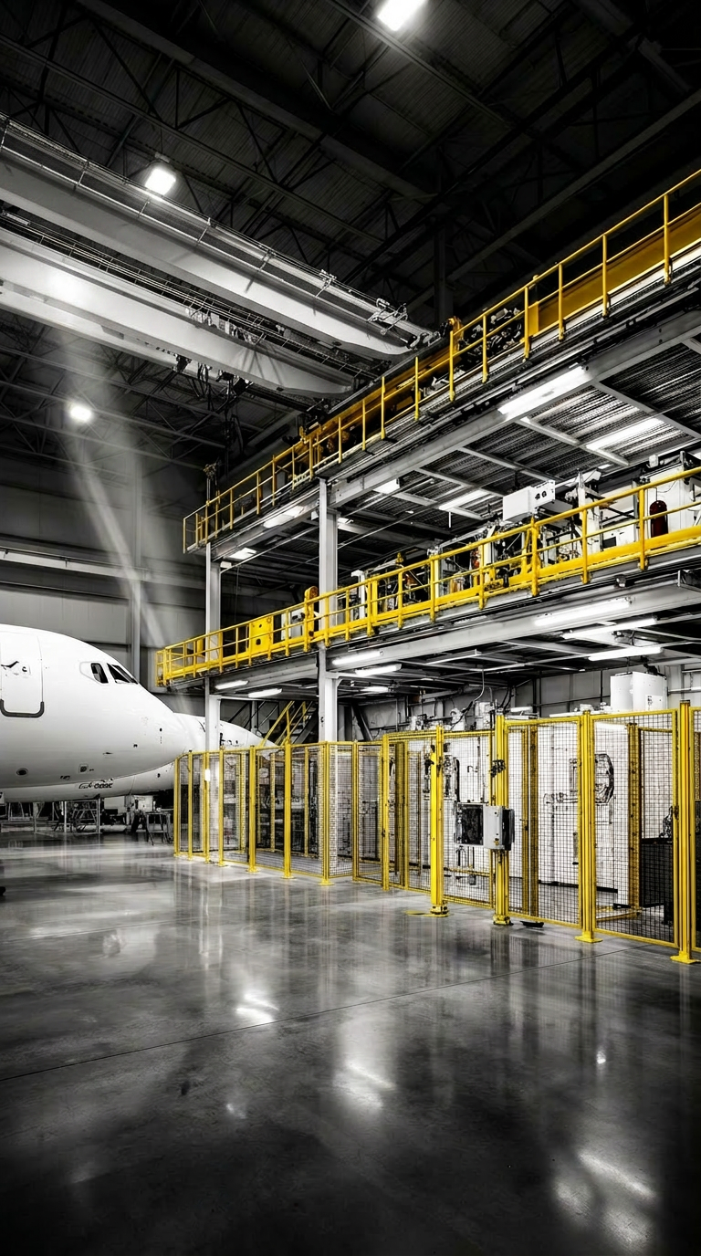
High-fidelity industrial infrastructure for Montreal's plant floors.
Custom mechanical engineering and design for the Greater Montreal manufacturing sector. We draft, fabricate and install load-bearing platforms, machine safety guarding, and precision vertical access systems.
Type: Mezzanine + Guard Cell
Site: Montreal, Saint-Laurent
Capabilities
Every component is drafted to CSA-S16-19 standards and validated through structural FEA analysis before fabrication.
Pick a discipline to see scope, applicable codes, and recent reference projects:
Machine Safety Guarding
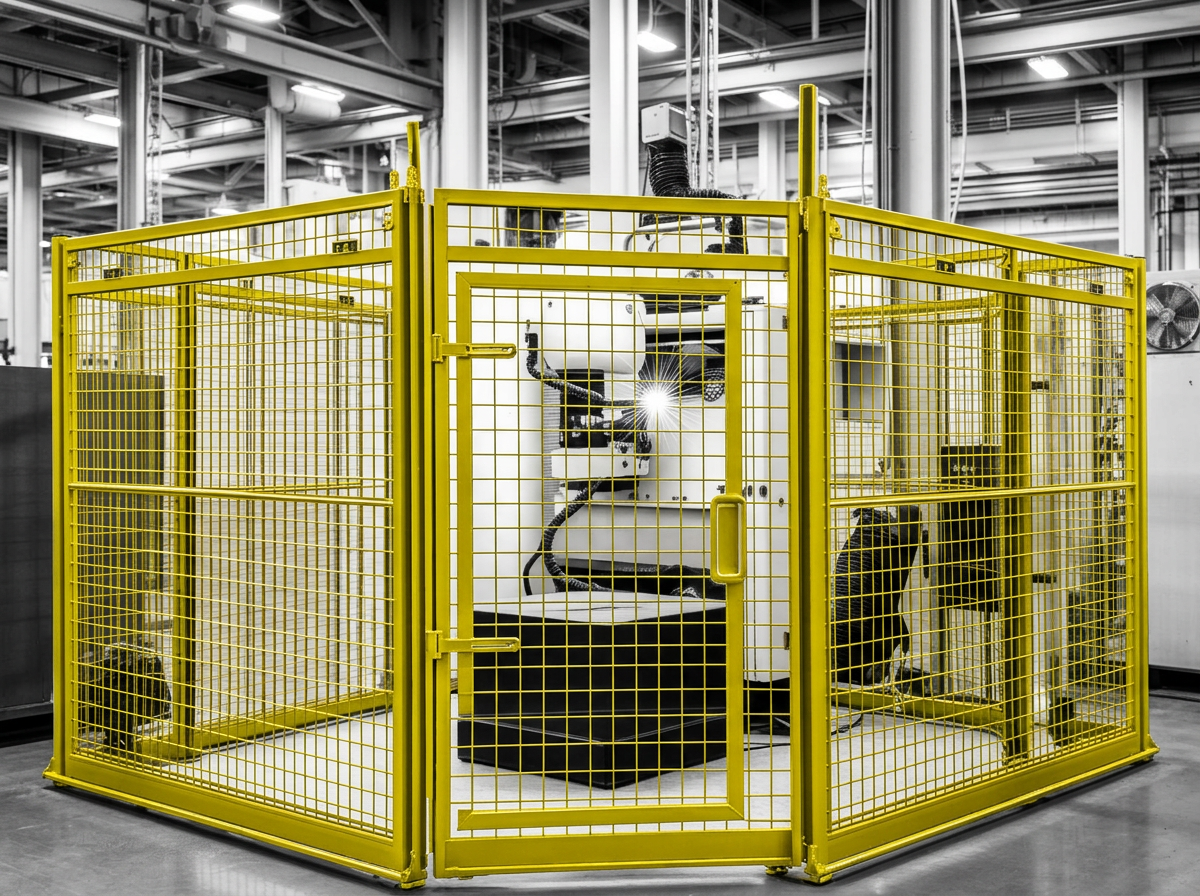
[ISO 14120] Interlocked perimeter fencing and fixed barrier systems designed for high-cycle robotic and CNC cells.
Platforms & Stairs
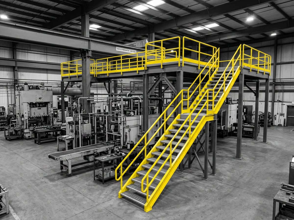
[NBC 2020] Mezzanine access, catwalks, and industrial stair towers in galvanized steel or architectural aluminum.
Custom Tooling & Jigs
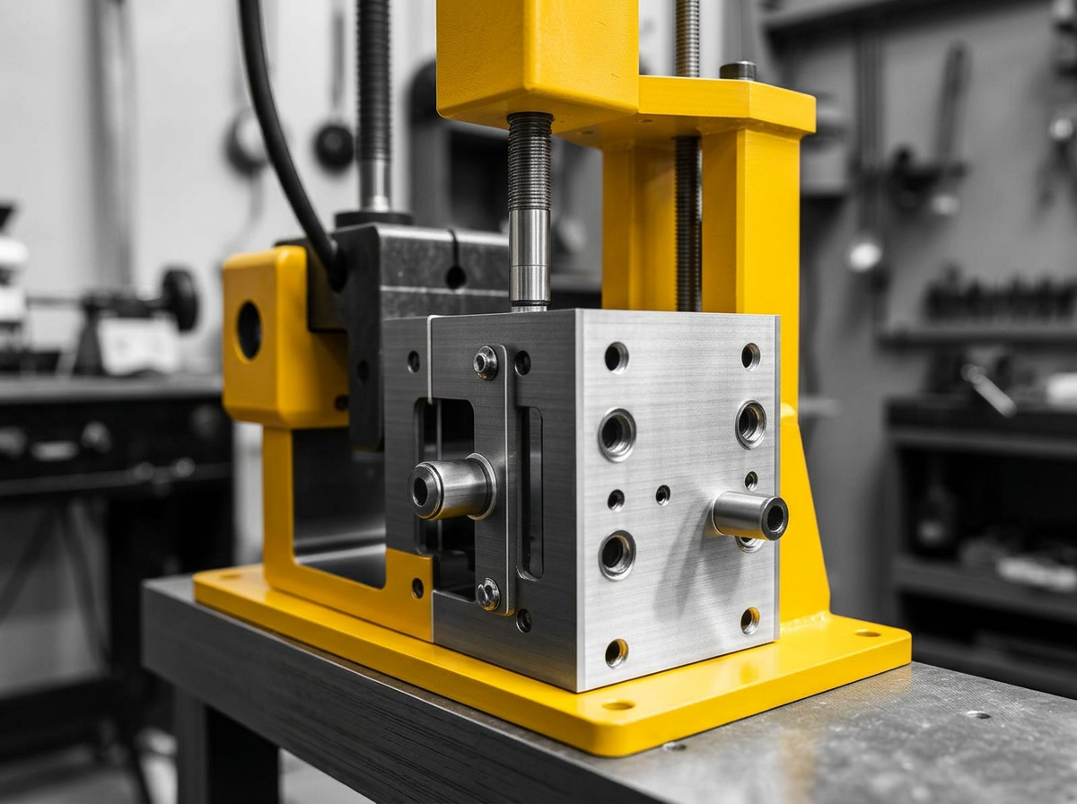
[ASTM E8] Precision jigs and ergonomic fixtures for assembly lines requiring non-standard integration.
Inspect a reference platform.
Drag to rotate. Scroll to zoom. A representative mezzanine cell with integrated guard rail, toe-kick and access stairs — the same building blocks we engineer for Greater Montreal plant floors.
- DECK4.0 × 3.0 m
- RAIL_HEIGHT1050 mm
- MACHINING_TOL±0.125 mm
- WELDING_TOL±2.5 mm
- CODECSA-S16-19
TYPE: SERVICE_PLATFORM // HYDRAULIC_ACCESS
DECK_H: 2400 mm // SCALE: 1:1
DRAG // SCROLL // ROTATE
From first call to commissioning.
- STEP_P1
Site walk & measure
I come to your floor with a tape, a notebook, and (when needed) a 3D LIDAR. We map clearances, anchor points, utilities, and traffic patterns before a single line is drafted.
- STEP_P2
Concept & feasibility note
Within five business days you receive a 2-page note: constraints, code references (CSA, NBC, CNESST), 2–3 sketched options, and an honest budget envelope. A preliminary design is also sent for your approval before detailed work begins.
- STEP_P3
Detailed design & calculations
Autodesk Inventor Professional 2026 3D models, FEA on critical members, and full GD&T fabrication drawings. Every load case is documented and shareable with your insurer or PE.
- STEP_P4
Fabrication oversight
I source through the Axya platform to match the best price to the lead time the project actually needs, then work with a vetted shortlist of Montreal-area welders and machinists. Weekly shop visits, weld inspection, and dimensional QA before anything ships.
- STEP_P5
Install & sign-off
On-site during install with RBQ-licensed installation partners — Gastier, Courtval, SIS, Dawco, Lilja and Industrie-L — anchor torque verified, and a complete handoff package: STEP, DWG, stamped PDFs, operator manual, and CNESST risk assessment.
Have a drawing, a problem, or just a square footage?
Send the brief. A senior engineer reviews every inquiry and responds within one business day with a feasibility note and ballpark range.